
Flexilink is designed for implementation in 21st century digital systems, in which packet forwarding is implemented in hardware and memory is much more plentiful than when Internet Protocol was developed. The information needed to route packets is carried separately from the packets themselves; this
It supports ultra-low latency live streams; these are needed for some of the new services that 6G aims to support, and also provide a better service for audio and video. They can be multicast to an unlimited number of destinations, and can also be used for file transfer, eliminating the need for the kind of empirical throughput testing that is a feature of TCP.
Flexilink grew out of a project to implement audio networking over ATM at the BBC, including implementing switches tailored to the needs of live audio and using Ethernet as an ATM physical layer (standardized by the Audio Engineering Society as AES51). It retains the useful features of ATM, and particularly of the way in which it was implemented in the BBC project to support live media, while jettisoning the unsuccessful aspects. It also has ancestry in a ring network technology that was used in industrial applications and in PC networking towards the end of the 20th century.
Whereas many packet networks are designed only to carry data between computers, Flexilink is also designed to meet the rather different requirements of live digital audio and video, which form an increasing proportion of the traffic on today's networks.
A prototype implementation exists and is being used in research at Birmingham City University and elsewhere. The main components of the technology are in the public domain and are not believed to be subject to IPR claims.
In Flexilink networks, the information needed to route packets is carried separately from the packets themselves. This reduces the size of the packet header by an order of magnitude, and supports authentication of the communicating entities before the data path is set up.
It also greatly simplifies the process of forwarding the packets in switches, allows different addressing mechanisms to be used without changing the packet format, and supports mobility without needing artificial devices such as IP-in-IP tunnels.
There is a separate service for constant-bit-rate traffic such as audio and video, offering very low latency as standard. This service can also be used for file transfer, where it eliminates the need for the kind of empirical throughput testing that is a feature of TCP (see 1.5).
Each packet is part of a "flow", and the packet header only needs to contain a locally-significant identification of the flow to which it belongs, along with packet-specific information such as the length. Information about the flow is conveyed by control plane messages, which can carry much more explicit detail than can reasonably be included in packet headers, and do not need to be constrained to use a particular form of addressing. The rationale behind this is as follows:
In practice, most IP packets are part of a TCP or RTP session.
The label identifying a flow is equivalent to the socket handle in the "sockets" API.
The memory needed to store information about each flow is no longer a scarce resource; memories are typically about 1 million times as big as they were when the technology on which IP is based was developed. Moreover, most of the information is only needed in the control plane, so does not need to be in fast memory.
Routing tables in the forwarding plane do not need to store routes to all possible destinations.
The service experienced by a packet in an IP network often depends on the flow to which the packet is identified as belonging; this identification is typically assembled from 13 bytes of information in five separate fields in the header.
Separation into control and data (or forwarding) planes is already a feature of mobile networks, and of SDN, and also of the internal structure of most network switches.
Thus flows are a feature that is in practice also present in IP networks, but in Flexilink they are made much easier to implement and to control. The control plane is assumed to be implemented in software running on CPUs, while the forwarding plane is assumed to be implemented in hardware (or "logic": FPGA for prototyping, SoC for production). This division of labour allows switches to be more energy-efficient than if they had to include a processor fast enough to examine every packet, especially as line speeds increase.
In the control plane, each flow has an identifier which (unlike an ATM call reference) is the same everywhere in the network. This makes it easy to detect routing loops, rendering protocols such as Spanning Tree unnecessary.
Applications are able to participate in control plane negotiation, for instance to specify the bandwidth required for a media stream and maybe offer a choice of trade-offs between quality and bandwidth in the case of compressed media. Control plane messages also carry metadata between the endpoints, including information on coding formats; thus they carry the information which in IP networks is carried by SIP and SDP.
Flexilink provides two services, referred to as "basic" and "guaranteed". Each has its own packet format, and on point-to-point wired links the two are multiplexed together, with the guaranteed service having priority and basic service packets able to use all the bytes that are not occupied by guaranteed service packets. The multiplexing is done in a way that avoids any requirement for fragmentation headers.
The guaranteed service is designed to offer the lowest possible latency for continuous media such as audio, video, and control loops (including "tactile internet"). Point-to-point links are formatted into "allocation periods", and each guaranteed service flow is assigned one or more packet "slots" in each period. To keep the latency to a minimum, the allocation periods of all links are phase-aligned; a very simple mechanism for this has been found to be effective.
Routing of guaranteed service flows is thus TDM-like, with a fixed latency for each flow and no need to examine the packets in order to route them. (This will potentially be useful for switching in the optical domain.) The service is similar to that from cross-point audio and video routers, and flows can be multicast by simply setting multiple outputs to "take" from the same input. Because each flow is assigned its own slots, it cannot be affected by traffic on other flows, and no further policing or traffic shaping is necessary.
The basic service is intended for the kind of bursty, unpredictable traffic that occurs with communication between computing processes, such as when downloading web pages. The maximum packet size is similar to Ethernet, but the minimum payload size is just one byte and no gap is required between packets. The packet header is similar in size to an MPLS label. In the prototype implementation, the service is "best-effort", with only one priority level, and only one output queue per port, because flows requiring QoS are assumed to use the guaranteed service. However, it would be possible to support multiple traffic classes, resource reservation, traffic shaping, etc, in the control plane messages and routing tables if required; note that this does not require any additional information in the packet header. Similarly, the current implementation does not support multicasting of basic service packets but that could be added if required, as could explicit congestion notification (ECN).
The basic service may be connection-oriented, in which case it is one-to-one (and flows are usually connected in pairs to form a bidirectional path), or connectionless, in which case it is many-to-one; see 3.3 for more detail.
A basic service packet can be carried over Ethernet or UDP by encapsulating it in an updated version of the format specified in AES51, and legacy packet formats can be carried over the basic service service by adding a basic service packet header to the front: see 7.
Guaranteed service packets can be carried over other network technologies (see 7.2). The service they experience will depend on the facilities provided by the host network, and where packets pass from the asynchronous service to the guaranteed service there is additional buffering which will add to the latency.
Control plane (signalling) messages are carried in basic service packets. Signalling flows get a higher priority than other basic service flows, so an overload of basic service packets cannot prevent control plane messages getting through. In the prototype implementation, signalling flows are only connected between adjacent network elements, so they do not go through the basic service packet forwarding mechanism; also, an overload of control messages from one neighbour cannot prevent control messages from other neighbours getting through. Protection for control messages between non-adjacent units (e.g. to or from an SDN controller) is for further study.
The basic service has similar characteristics to IP networks, i.e. transit time will increase if there is congestion, and packets may be lost if buffers in intermediate nodes overflow. It is therefore the appropriate service for transport protocols such as TCP to use.
However, a data transport protocol could also be designed to run over the guaranteed service. The fixed bandwidth of a guaranteed service flow (which can be set to the maximum that the two endpoints and the intermediate network links can support) removes the need to adjust transmission rates based on the time it takes for acknowledgements to arrive. Packets will not be lost due to buffer overflow, so it is not necessary for the recipient to send frequent acknowledgements; in the case of a file transfer, notification of missing or corrupt packets or confirmation at the end of the transfer that the whole file has been correctly received should suffice, and these messages can be carried in the control plane, without needing to set up a reverse flow in the forwarding plane. A file could also be multicast to a potentially large number of recipients. The benefits of this version would be most noticeable for large transfers; the information in the control plane messages would allow the network to route the flow over high-capacity services such as WDM if appropriate.
The forwarding plane carries packets which consist of a header and a payload. Each packet belongs to a "flow", which defines the action to be taken at each point on its journey.
The payload is a byte string which is carried to the endpoint(s) without being inspected or altered, except that it may be possible for occasional bit errors or loss of an entire packet to occur due to faults in equipment or corruption of transmitted signals. Also, basic service packets may be lost because of buffer overflow. Mitigation of errors (e.g. by forward error correction or by detection and retransmission) is assumed to be implemented in the end systems. Which measures are appropriate will depend on the application; for instance: in a data file transfer, accuracy is more important than timeliness, whereas timeliness is more important than accuracy for live audio and video. Control plane messages can report an estimate of the reliability of equipment and transmission media along the route, and hence the likelihood of errors.
The header codes the payload length and, for basic service packets only, a local identification of the flow.
The routing mechanisms for the two kinds of flow are different, and in the prototype implementation follow different paths through the logic, although they share the links between network elements (see 2.4.1).
The guaranteed service was originally envisaged as supporting slots (and packets) of any size up to about 4K bytes, with the slot size being in steps of 2 or 4 bytes so that small packets (such as single audio samples) could be carried efficiently and large packets could be carried without fragmentation. This was partly to get away from one of the drawbacks of ATM, that its fixed-size cells were too large for some kinds of traffic and too small for others. However, it was found to have a number of disadvantages compared to fixed-size slots able to hold one packet each.
The maximum size of a guaranteed service packet needs to be small so that a flow's slot allocations can be more evenly spread, to avoid blocking off large areas in the allocation period, which would increase the latency experienced by other flows and hence also require a bigger packet buffer in switches. On the other hand, slots need to be at least as big as the internal data paths in a switch, which need to be quite wide to provide the throughput needed in today's networks. In the prototype implementation, after some experimentation a slot size supporting up to 63 bytes of payload was chosen. This is distressingly close to the size of an ATM cell, but unlike ATM the unused bytes at the end of a slot are not wasted but are used for basic service packets. Also note that an MPEG2 Transport Stream packet fits neatly into three guaranteed service packets. The header is a single byte formatted as:
1 bit: odd parity
1 bit: flag f (see below)
6 bits: n, the number of payload bytes
A null packet, or a slot that does not contain a packet, has f = 1 and n = 0. The flag f is not used for routing, but is available for use by endsystems; if it is used to guide reassembly of longer messages, it should be set to 0 in the last fragment of a message and 1 in others, so that adding or dropping null packets will have no effect.
Ideally this format would be used throughout the system. Note that the header does not change when the packet is forwarded.
A basic service packet header carries two pieces of information: the payload length and a "flow label", which is a locally-significant handle on the flow. In the prototype implementation, each of these is coded as a 13-bit value and a 3-bit CRC. It would be possible to also include a "congestion experienced" flag. The flow label, being local to the link on which the packet is transmitted, is changed each time the packet is forwarded. If a packet is forwarded between links that have different header formats the entire header may need to be replaced.
The maximum length is 2000 bytes, so that Ethernet envelope frames can be carried without fragmentation.
See 7.1 for the definition of a physical link.
The prototype implementation is over point-to-point links using full duplex 1 Gb/s Ethernet physical layer (copper or fibre). This uses the Ethernet PHY as a way of transmitting a byte stream; it has its own MAC layer, which is different from the Ethernet MAC layer. See 7.2 for a transmission format that uses the standard Ethernet MAC layer.
A frame on a point-to-point 1Gb/s Ethernet link consists of:
The AES51 header consists of a "type" byte which shows the frame's location within the allocation period and a 32-bit "timing" field. The format of the timing field has been changed from the specification in AES51-2006, to be compatible with PTP. The FCS is used only to check the integrity of the link, and is different from the Ethernet FCS so that frames will not be interpreted as Ethernet packets.
The data on the link can be regarded as divided into three levels: framing, foreground, and background. The framing level consists of the preamble, SFD, AES51 header, FCS, and inter-frame gap. The foreground level consists of the first byte of each slot, and the payloads of all guaranteed service packets.
The background level consists of all other bytes, i.e. the last 63-n bytes of each slot (where n is as in 2.2 above) and the "trailing" bytes. It carries basic service packets and "idle" bytes, which are transmitted when there are no basic service packets in the queue; they are coded as 0xFF, which is not a legal coding for the first byte of a basic service packet header.
Figure 1: Paths through a Flexilink switch
Figure 1 shows the typical paths that packets take through a switch. The receiving side MAC logic separates out the foreground and background data, and the transmitting side merges them together; in both cases the background stream is intermittent because it pauses whenever there is a byte that is on one of the other two levels.
Note that a continuous stream of frames is always transmitted, as with SDH. If there are no packets to be sent, the frames are filled with "idle" bytes with an empty slot header every 64th byte.
Any point-to-point link that can carry a byte stream can be used as a bearer for frames similar to those described in 2.4.1.
Standards for transmission over DECT-2020 NR and 5G NR are under development; transmission over other radio channels is for further study.
Transmission over fibre, in the case where guaranteed service flows are switched in the optical domain without examining the packet headers, is also for further study. Unused bytes in allocated slots would not be able to be used for basic service packets, although unallocated slots would be. With the current state of the art, slots would need to be much larger than 64 bytes.
Control plane messages use a tag-length-value format. This makes it easy for recipients, even those implemented with small microcontrollers (such as some IoT devices), to parse the message and extract the information they need, while also making the encoding fully extensible. It is also more space-efficient than text-based coding formats, and can easily be translated into a human-readable text form when required for debugging purposes.
The message formats and protocols used in the prototypes were based on IEC 62379-5-2, but an updated specification is now under development as ETSI GS NIN 005.
Each physical network element (switch or end equipment) has a 64-bit globally unique identifier or "unit id". This can be an EUI-64; EUI-64s always have 00 in the least significant 2 bits of the first byte, and additional forms with nonzero code points in those two bits are also defined, including temporary identifiers that can be issued to end equipment that does not have its own, and identifiers based on Private Enterprise Numbers instead of OUIs.
Each flow (see 1.3) has a 128-bit globally-unique identifier partitioned into:
64 bits: unit id of the "owner", the unit that created the flow identifier
32 bits: call reference
7 bits: route reference
1 bit: direction (1 = towards owner, 0 = away from owner)
24 bits: flow reference
The first 96 bits form a "call identifier". The owner is responsible for ensuring that the call identifier is unique.
A "call" can be composed of several flows, for instance a TV programme may be composed of separate flows carrying low-resolution video, additional information to create a higher-resolution image, several different audio streams, captioning text, and metadata; some destinations might only take a subset of the flows, e.g. only the low resolution video and one of the audio streams. Flows that are part of the same call have the same call identifier and are distinguished by their flow reference and direction.
Several copies of a flow may be transmitted over different routes, where this is required for resilience. The different copies have the same flow reference and are distinguished by their route reference.
The globally-unique flow identifier makes it easy to avoid setting up routes that include loops, and to detect whether routes that are duplicated for resilience actually follow separate paths.
Flow identifiers are only used in the control plane.
A wide variety of types of address or identifier can be used. The called party can also be identified by a service it provides or a piece of content the caller wishes to access.
See 6 for more details.
The FindRoute control plane message type is used to set a flow up. The procedure is initiated by a unit (network element) which will be at one end of the route; it sends a FindRoute request message to one or more neighbouring units, which in turn process it and forward it on until it reaches a unit which will be the other end of the route.
With the small switches that form the prototype implementation, each unit simply floods the request to all its neighbours, except where that would form a loop. The globally-unique flow identifier makes loops easy to detect. In a network with larger switches, additional information, either from a central resource similar to an SDN controller or distributed by a peer-to-peer protocol, should be used to limit the number of neighbours to which a request is forwarded.
There are two replies to a FindRoute request: an immediate acknowledgement, followed later by either a FindRoute response or a ClearDown request, the latter indicating that the route cannot be set up. Further messages may be exchanged after the response: "confirmation" in the same direction as the request and "completion" in the opposite direction.
Processing of the messages includes setting up the forwarding plane flow in the routing tables. In some cases this needs to be done by the later messages in the sequence, for example so that data cannot flow until authentication procedures have been completed (see 5). In other cases it is set up by the earlier messages to reduce the latency between initiating the request and data flow beginning. Note that setting a flow up in the forwarding plane is very simple, so the cost of setting one up early in the process and then clearing it down again if it is not required is very small.
The basic service supports many-to-one flows, whereby packets arriving at a switch from different sources may be forwarded on the same flow. These flows can be used, in a similar way to MPLS Forwarding Equivalence Classes, to carry IP packets. The way they are administered means there is no need for a "time to live" field in the packet header; the details of the procedures are for further study.
Network elements can record when the most recent packet was forwarded on each flow, and clear it down if nothing has been seen for a specified time. Note that this is very similar to route caching in IP switches.
FindRoute messages can include a wide variety of information both for the network and for the units at the ends of the flow, including information to help in choosing the route and to tell the recipient the format of the data. They can also include charging information, which might be used for micropayments for access to content or services as well as for traditional call charging.
Each link between network elements is formatted into "slots", and the slots are grouped into "allocation periods". Each guaranteed service flow is allocated one or more slots per allocation period. The framing on the link shows where each allocation period starts and a flow's allocation is of the same set of slots in each period. The flow to which a guaranteed service packet belongs is identified by the packet's location in the allocation period.
In the prototype implementation, an allocation period contains 1936 slots and lasts about 1 ms, so the allocation repeats about 1000 times per second. The minimum allocation for a flow is one slot per period, i.e. 1000 packets per second. A longer period would allow finer-grain allocations but increase the size of the routing tables, e.g. doubling the length of a period to 2 ms would reduce the minimum allocation to 500 packets per second but double the size of each port's routing table. The standards allow each link to have a period of 0.5, 1, 2, 4, 8, 16, or 32 ms.
In practice the nominal length of an allocation period is a multiple of 0.99968 ms rather than 1 ms. This allows for some tolerance in the clock rates while still guaranteeing that a flow that is nominally 1000 packets per second will be able to carry at least that number, even if the reference used for the frame rate on the network is slow by up to 150 ppm and the reference used by the source of the data is fast by the same amount.
To achieve the minimum latency at a switching point, there needs to be a fixed phase relationship between incoming and outgoing allocations. This is referred to in the prototype implementation as "tight" frame alignment.
When a link first comes up, it can only carry basic service flows. Negotiation via SyncInfo control plane messages establishes whether the two sides have a common reference; if not, further negotiation arranges for the subnetwork on one side of the link to take its timing from the other.
The links used to convey frame timing form a spanning tree, but there is no need for a "spanning tree protocol" to configure the network; changes only occur when links come up or go down, and once a link is on the tree it remains on the tree until it goes down.
Any part of a flow can be re-routed without affecting the rest of the flow. Thus if a mobile device changes its point of attachment, e.g. moves to a different cell, the flows connected to it can be switched from the old cell to the new without the systems with which it is communicating, or higher-layer processes in the device itself, needing to be aware of any change.
When a server receives an incoming call it is supplied with the flow label to be used in packets to the client; it does not need to know the client's address and is therefore unaffected if the client's location changes.
The FindRoute messages that are used to set calls and flows up may include as much or as little identification of the caller as is required. Client and server can exchange authentication information in these messages, and reject the call if necessary, before setting the flow up in the forwarding plane. Alternatively, a server can allow clients to be completely anonymous. There are also facilities for the network to report whether a call comes from a trusted source.
Flow labels are local to each link, and are controlled by the entities (switch or endsystem) at either end of the link via control plane messages. A packet arriving on a particular flow can therefore be assumed to be covered by any authentication etc procedure performed when the flow was set up.
Using domain names directly in addresses (see 6) potentially allows DNS servers to be more resilient to "spoofing".
As noted in 1.4 above, guaranteed service flows have reserved capacity with which other traffic cannot interfere.
An overload of control plane messages coming into one port of a switch cannot stop control plane messages being received on other ports, and (provided the switch serves the ports in rotation) will have only a minimal effect on the service experienced by other ports.
FindRoute messages can include a specification of the throughput expected on each basic service flow. A switch could monitor the actual throughput of each flow and tear down flows that misbehave, or apply other traffic policing measures.
There are no "address" fields in packet headers.
The CalledAddress field in FindRoute control plane messages supports a wide variety of addressing schemes, and there are a large number of reserved code points which would allow more to be added. As well as traditional addressing schemes such as IPv4, IPv6, and E.164, which identify an interface, and the 64-bit unit identifiers for physical equipment (see 3.2.1), other means of identifying the target of the call can be supported, such as content-centric addressing, which might connect either to the system that hosts the content or to some nearer device that holds a cached copy. Domain names could be used directly, instead of needing a separate process to convert them to IP addresses.
An address can be composed of an identifier preceded by one or more locators; the locators are processed in sequence, and each identifies the context within which the next part of the address will be interpreted. Examples of locators are the address of a gateway and the identifier of equipment that hosts a service. This allows addresses that have local scope to be used in global contexts.
The flow labels in basic service packet headers are local to each link, and can be tailored to the requirements of different kinds of link, for instance by using a larger field on links that are expected to carry a larger number of flows. A group of basic service flows can be routed through a core network as a single flow by simply adding another header, in a similar way to an MPLS "push" operation.
A "physical link" is a connection on which frames are tightly phase-aligned as described in 3.4.2.
An "island" consists of network elements that are connected to each other by physical links.
A "virtual link" is implemented by tunnelling flows across other networking technologies.
A "gateway" is a connection to a network that uses a different technology.
A "client" is an endsystem that is connected to a Flexilink network via a different technology.
Figure 2 illustrates some of these concepts.
Figure 2: Flexilink topography
Basic service packets are carried over virtual links by encapsulating them either directly in Ethernet or in UDP as shown in Figure 3. Similar formats could be used with other services such as MPLS.
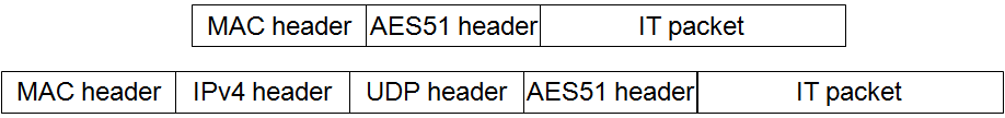
Figure 3: Encapsulation of basic service packets on legacy networks
Guaranteed service packets are carried by encapsulating them in a basic service packet which is carried over a virtual link; at the receiving end there is a de-jitter buffer for each guaranteed service flow, and the label in the basic service packet header shows to which flow the guaranteed service packets belong. A null guaranteed service packet is generated if the de-jitter buffer is empty when a packet is required for onwards transmission.
"Loose" frame alignment, whereby one island takes its frame timing from the other, is used to ensure that packets do not accumulate over time in the de-jitter buffer.
This provides a migration path whereby applications can be developed using the new technology before it is ubiquitous. The service experienced by guaranteed service flows will gradually improve as virtual links are replaced with tightly-aligned physical links.
In the current implementation, if terminal equipment which uses IP is connected to an Ethernet port, and elsewhere in the island there is a port connected to an IP network, a tunnel is set up in which each Ethernet packet is carried as the payload of a basic service packet. This has the advantage of simplicity and works well in situations where all traffic between the terminal equipment and IP destinations can go through a single gateway. The terminal equipment can also set up a virtual link, through which it can access destinations (such as management agents) within the Flexilink network.
For more complex situations, where different IP addresses need to be routed through different gateways, the connectionless service (see 3.3.2) should be used to carry the IP datagrams, with the Ethernet MAC headers being stripped on entry and added on exit; this requires ARP to be implemented at the entry and exit points.
Tunnelling of MPLS has not yet been investigated, but should be straightforward.
This provides a migration path whereby parts of an existing network can be replaced with the new technology without affecting applications developed for the previous technology.
Gateways could also provide translation further up the stack, for instance by connecting RTP-based standards such as AES67, EBU ACIP, and SMPTE 2022 to guaranteed service flows, with interworking between SIP/SDP and Flexilink signalling, and between PTP and the timing information in the AES51 headers.
------------- ooo OOO ooo -------------
Copyright ©2016-2025 Nine Tiles